acf domain was triggered too early. This is usually an indicator for some code in the plugin or theme running too early. Translations should be loaded at the init action or later. Please see Debugging in WordPress for more information. (This message was added in version 6.7.0.) in /www/wwwroot/yuzantech.com/wp-includes/functions.php on line 6131unlimited-elements-for-elementor domain was triggered too early. This is usually an indicator for some code in the plugin or theme running too early. Translations should be loaded at the init action or later. Please see Debugging in WordPress for more information. (This message was added in version 6.7.0.) in /www/wwwroot/yuzantech.com/wp-includes/functions.php on line 6131dynamic-content-for-elementor domain was triggered too early. This is usually an indicator for some code in the plugin or theme running too early. Translations should be loaded at the init action or later. Please see Debugging in WordPress for more information. (This message was added in version 6.7.0.) in /www/wwwroot/yuzantech.com/wp-includes/functions.php on line 6131


Operating Voltage:DC12V
Current Consumption:≤ 15mA
Alarm Indicator:Red LED
Sensor:Infrared photoelectric sensor
Operating Temperature:-10°C~+50°C
Environmental Humidity:Maximum 95%RH (no condensation)
Anti-RF Interference:10MHz-1GHz 20V/m
Alarm Output:Normally open/normally closed optional. Contact capacity DC28V 100mA
| Operating Voltage | DC12V |
| Current Consumption | ≤ 15mA |
| Alarm Indicator | Red LED |
| Sensor | Infrared photoelectric sensor |
| Operating Temperature | -10°C~+50°C |
| Environmental Humidity | Maximum 95%RH (no condensation) |
| Anti-RF Interference | 10MHz-1GHz 20V/m |
| Alarm Output | Normally open/normally closed optional. Contact capacity DC28V 100mA |
| Reset Method | Automatic reset/power-off reset optional |
| Coverage Area | When the space height is 6m~12m, the protection area of one detector is 80m² for general protection sites; when the space height is below 6m, the protection area is 60m². Specific parameters shall be subject to the Code for Design of Automatic Fire Alarm Systems GB50116-98. |
| Overall Dimension | 104mm (diameter) * 51mm (height) |
This product is a photoelectric smoke detector, which works based on the principle of sensing smoke particles. Adopting a unique structural design and photoelectric signal processing technology, it has the functions of dustproof, insect-proof, anti-external light interference, etc., and ensures the stability of the product from the design. This product has a good response to slow smoldering or open burning visible smoke. It is suitable for smoke monitoring in indoor environments such as residences, shopping malls, hotels and warehouses.
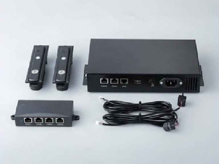
This product is a non-coded smoke detector with a pair of switch output contacts, which can choose normally open or normally closed output according to actual needs. During normal operation, the indicator light flashes once every 9 seconds; when alarming, the indicator light is always on, and the alarm output contact acts at the same time.
Power-off reset/automatic reset optional
Infrared light point sensor
Alarm output N.C/N.O optional
Intelligent logic control to filter out various false alarms
Networking output/LED indicator alarm
SMT process manufacturing, strong stability
Dustproof, insect-proof, anti-natural light interference design
Metal shield, anti-RF interference (20v/m-1GHz)
1. Select a suitable installation location, generally installed on the ceiling in the center of the detector coverage area.
2. Connect the power line and signal line to the installation base. (Installation base “1” is the positive pole of the power supply; “2” is the negative pole of the power supply; “3, 4” are the alarm output contacts.)
3. Fix the installation base on the ceiling with screws.
4. Align the positioning bump at the bottom of the detector with the positioning groove of the installation base and rotate clockwise to install the detector.
1. The detector should be dustproof. The dust cover can only be removed after the project is officially put into use.
2. There should be no obstacles within 0.5m around the detector.
3. The horizontal distance from the detector to the air supply outlet of the air conditioner should not be less than 1.5m.
4. The horizontal distance from the detector to the wall or beam edge should not be less than 0.5m.
5. When installing detectors on the ceiling of internal walkways with a width less than 3m, they should be arranged in the center. The installation distance of detectors should not exceed 15m, and the distance from the detector to the wall should not be greater than half of the detector installation spacing.
6. The detector should be installed horizontally. If it must be installed obliquely, the inclination angle should not be greater than 45 degrees.
7. The detector base should be installed firmly and its wire connection must be reliable.
8. It is recommended to conduct a simulated fire test every six months to test whether the detector works normally.